Advanced Diploma in Industrial Control & Automation (ADICA)
-
9 Major Brands Of PLC’s ( Allen Bradley, Siemens, Mitsubishi, Omron, ABB, Fuji, Delta, GE-Fanuc, Keyence)
-
2 Major Brands Of SCADA’s( WonderWare Intouch, King view)
-
3 Major Brands Of HMI’s ( Siemens, Omron, Delta )
-
1 Major Brand of VFD ( Delta )
-
Major Brands Of DCS (Emerson DeltaV DCS, ABB 800XA DCS, Honeywell Experion C300 DCS)
-
Field Instruments
Normal Track – 60 Days
3 Hrs Per Day
Fast Track – 30 Days
6 Hrs Per Day
Training Method:
All of our engineer’s are Industrial experienced engineers and we will give training based on our existing projects.
Overview:
-
Basic of Electronics, Electrical, Instrumentation, Programming, Process
-
Understanding for Automation & Control
-
History of PLC / SCADA
-
Basic components of Automation
-
Hardware / Software classification of Automation
-
Application of Industrial Automation
-
Job opportunity for PLC / SCADA
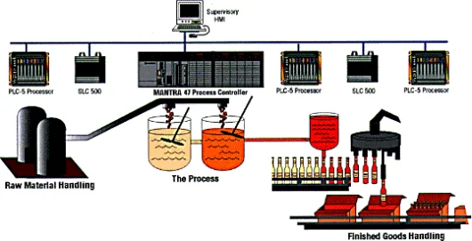
Course Content: PLC
-
Introduction to PLC’s
-
Architecture of PLC
-
Application and Advantage of PLC
-
Automation Concept and basic design
-
PLC programming
-
Introduction of Ladder Logic
-
Introduction of SFC
-
Introduction of Instruction list
-
Programmable Logic Controllers basic’s
-
Software / Hardware Introduction
-
Programming of PLC using 1131-3 Languages (LD, FBD, IL, etc.)
-
Developing the PLC programming from Control Narratives
-
Creating & Editing Ladder Logic Program
-
Developing industry oriented application programs using PLC Programming Software
-
interfacing PLC with various field input/output devices
-
PLC Fault Finding, Trouble Shooting
-
Forcing I/O’s
-
Detailed sequence of wiring
-
PLC Control Panel Wiring
-
Interfacing with Relay logic
-
Hands on Experience from Real time application
-
Detailed Functions blocks and Wiring concept of Digital & Analog I/O modules
-
Fundamental of Basic Process Control
-
Implementation of Control Narratives
-
Transmitters / Transducer / mA Sources connect with PLC
-
Overview of Flow, Pressure, Level, Temperature Transmitters
-
Overview of Control valve and ON/OFF valves
PLC Lab Capacity:
-
Siemens PLC
-
Allen Bradley PLC
-
Schneider PLC
-
ABB PLC
-
Mitsubishi PLC
-
GE Fanuc PLC
-
Fuji PLC
-
Omron PLC
-
Delta PLC
-
Keyence PLC
-
Messung PLC
Industrial / Project Documents:
-
P&ID Diagram (P&ID)
-
I/O List
-
Cause & Effect diagram (C&E)
-
Control Narratives
-
Single Line diagram
-
Function Design specifications (FDS)
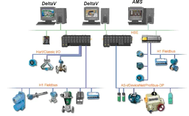
HMI:
-
Introduction to HMI
-
Architecture of HMI / MMI
-
Creating Slides/Screens
-
Images, Objects Configuration
-
Alarm Configuration
-
Live interfacing with PLC
SCADA:
-
Introduction to SCADA
-
Establishing master-slave control
-
Creating & Editing Objects
-
Creating Database / New SCADA Project
-
SCADA page design from P&ID Diagram
-
Alarm Configuration
-
Trends- Real Time & Historical
-
Database & DDE connectivity
-
Driver configuration
-
Live interfacing with PLC
-
Graphics Properties – Sizing, Filling, Blinking, Analog Entry, Visibility,Etc.
-
SCADA & PLC Interface used Different drivers
-
Understanding of P&ID diagram
-
SCADA Mimic page create from P&ID Diagram
-
Alarm / Events Configuration
-
Report generation
-
Modbus / Profibus / OPC
-
Data transfer from PLC/RTU , Report Generation
-
Process Graphics Development
-
Dynamic Object / Display Creation
-
Cause & Effect Matrix creation
-
Dynamo creation for display
SCADA Lab Software's:
-
Wonderware SCADA
-
Siemens WinCC SCADA
-
IFIX 32
-
KingView
-
AFCON (PCIM)
Human Machine Interface(HMI) Lab's:
-
Siemens
-
Mitsubishi
-
Delta
-
Omron
VFD:
-
Introduction to Drives & Motors
-
Architecture of VFD
-
VFD Programming
-
Interfacing PLC to VFD
-
Motor Speed Control using VFD
-
Checking the rated voltage, rated current, rated RPM
Variable Frequency Drives(VFD) Lab's:
-
Mitsubishi
-
Delta
-
Omron
DCS Training (Emerson DeltaV DCS or Honeywell Experion C300 DCS):
Trainers
Training Content:
-
DCS Introduction
-
System Overview
-
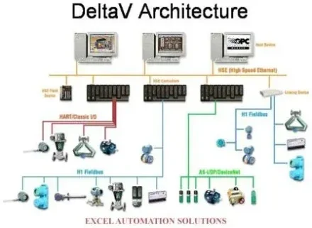
DCS Architecture Overview
-
Explorer
-
Operate
-
Control Modules
-
Program Types
-
Input / Output Configuration
-
Database
-
DCS System Architecture Design
-
Alarm Management
-
Field Instruments
-
HART Transmitter Configuration
-
Field bus Configuration
-
Serial / Modbus Configuration
-
Profibus Configuration
-
FBD / SFC programming
-
Communication Methods
-
Pre Commissioning procedure’s
-
Loop Checking
-
Control Loops – Normal, Cascade, Split
-
Loop Tuning’s
-
FAT / SAT procedures
-
Hardware Overview
-
Hardware design
-
Panel Design
-
I/O Generation
-
P&ID diagram Overview
-
Graphics Development
-
DeltaV Networks design
-
Process History view
-
Motor Control
-
Real time project Implementation
-
Project based learning
-
Commissioning Overview
-
Project Management
Field Instruments Training:
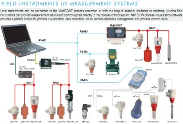
An instrument is a device that measures a physical quantity such as Flow, Temperature, Level, Pressure, Distance and Angle. Instruments may be as simple as direct reading thermometer or may be complex multi-variable process analyzers. Instruments are often part of a control system in refineries, factories, and vehicles. The control of processes is one of the main branches of applied instrumentation. Instrumentation can also refer to handheld devices that measure some desired variable. Diverse handheld instrumentation is common in laboratories, but can be found in the household as well. For example, a smoke detector is a common instrument found in most western homes.
Instruments attached to a control system may provide signals used to operate solenoids, valves, regulators, circuit breakers or relays. These devices control a desired output variable, and provide either remote or automated control capabilities. These are often referred to as final control elements when controlled remotely or by a control systems.
A Transmitter is a device that produces an output signal, often in the form of a 4 – 20 mA electrical current signal, although many other options using voltage, frequency, pressure are possible. This signal can be used for informational purposes, or it can be sent to a PLC, DCS, SCADA,ESD/SIS,FGS system, or other type of computerized controller, where it can be interpreted into readable values and used to control other devices and processes in the system.
A valve is a device for Controlling the passage of fluid/Pressure/Level through a Pipe or duct/Tank,especially an automatic device allowing movement in one direction.Two type of valve’s are used in industries,
-
Control Valve
-
On/Off Valve.
Control instrumentation plays a significant role in both gathering information from the field and changing the field parameters, and as such are a key part of control loops.
Syllabus:
-
Field Instruments Introduction
-
Filed Instruments Overview
-
Field Instruments Types
-
Pressure Transmitters Configuration
-
Flow Transmitters Configuration
-
Temperature Transmitters Configuration
-
Level Transmitters Configuration
-
Control Valve Configuration
-
On/Off Valve Configuration
-
Conventional type Transmitter
-
Wireless Transmitters Overview
-
Field Instruments Selection
-
Wireless Transmitters Configuration
-
Filed Instruments Calibrations
-
Filed Instruments range changing
-
375 Filed Communicator Overview
-
375 Filed Communicator Configuration
-
I/O List generation from Field Instruments
-
Filed instruments integrated with DCS/PLC systems
-
Field Instruments identify from P&ID diagrams
-
HART Type Transmitters and Control Valves
-
Field bus type Transmitters and Control Valves
-
Filed Instruments calibration from DCS and Marshaling panel
-
2-Wire / 3-Wire Transmitter overview and Configuration
-
ESD/SIS valve Overview